PLANT FRIENDS MKII
SENSOR
NODE
HARDWARE
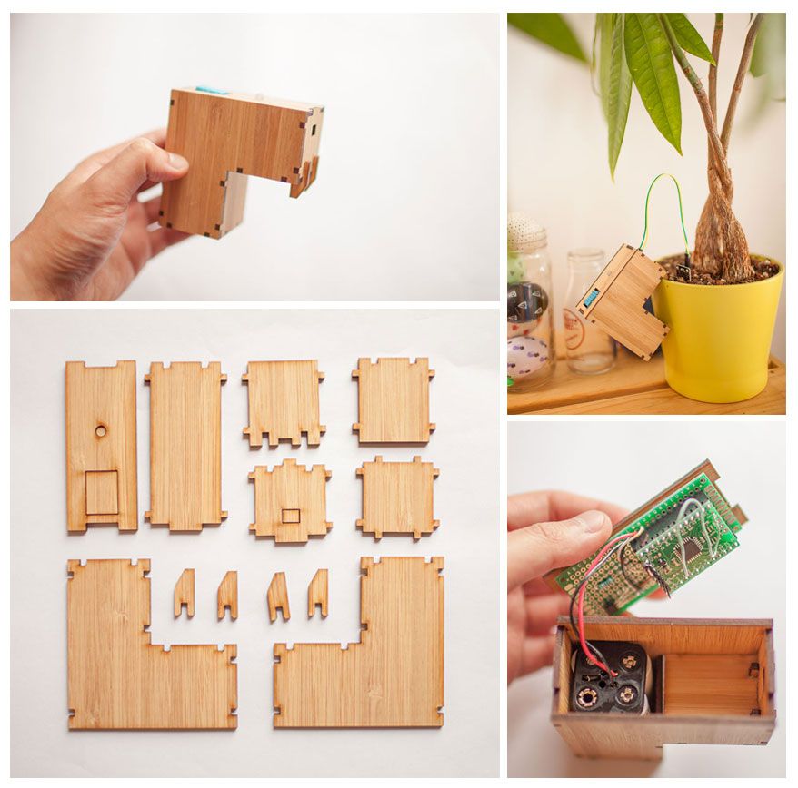
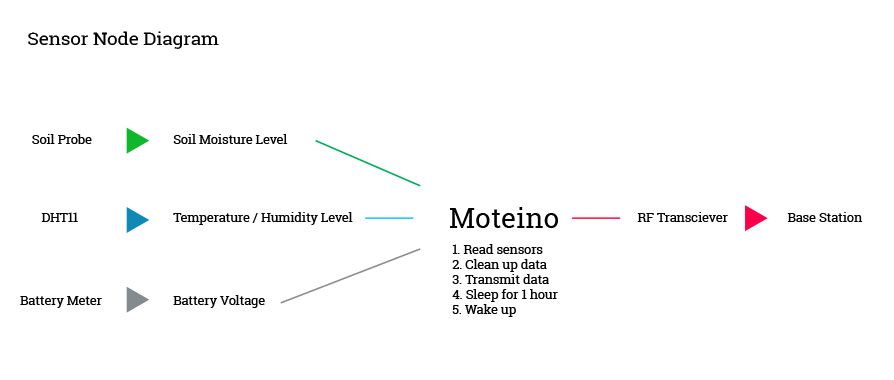
The sensor node is responsible for gathering soil moisture, temperature / humidity and battery voltage data and sending it to the base station. Let's look at the operational diagram for the sensor node:
This section is for those of you that bought my custom sensor node circuit board. If you are using a protoboard, scroll down.
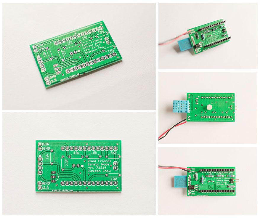
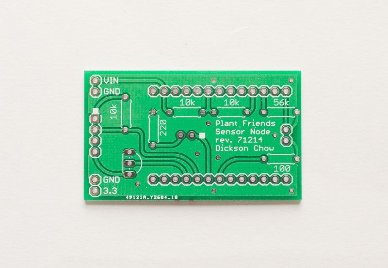
This is what the bare PCB looks like:
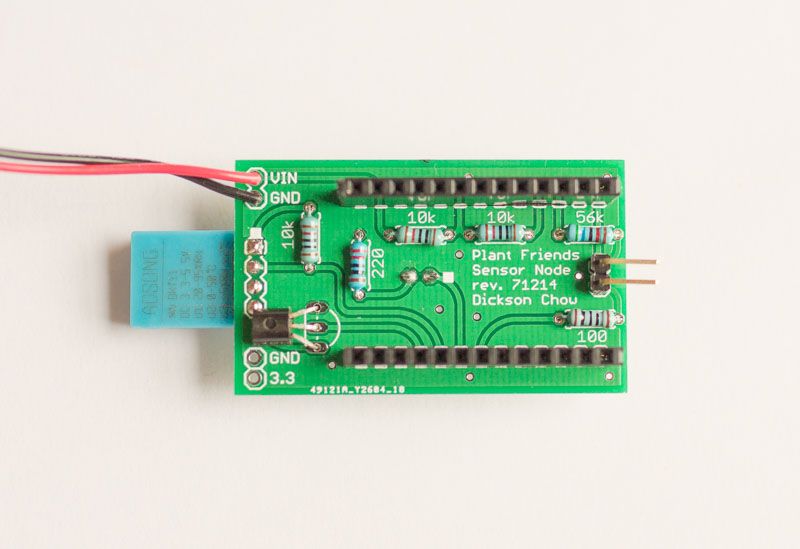
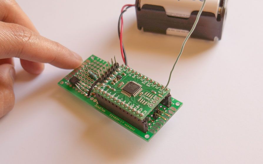
The assembled PCB:
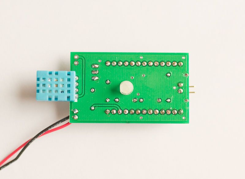
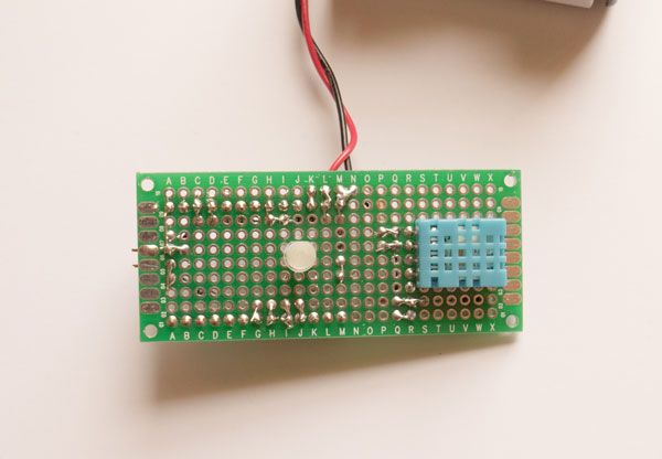
The back side of the assembled PCB:
Assembling the Plant Friends PCB is very straight forward. The resistor values and locations are already labeled at their respective places. I suggest you solder the resistors first, followed by the DHT11 sensor then everything else. For the LED and the DHT11, the anode (positive) pin position is marked with a white square. Solder the DHT11 sensor first, then the 2N2222 transistor. Look at the pictures and make note of the orientation of the 2N2222 transistor.
For the battery pack, connect the positive (red) wire to "VIN" and ground (black) to "GND". You'll need two-pin, 90 degree angled male header to connect to soil probe.
Measure the number of female pins (13 pins for each side) so it matches the number of male pins on the Moteino. Solder the straight female headers onto the circuit board.
I also broke out the 3.3v power out in case you need to power other 3.3v devices. This 3.3v is supplied from the Moteino.
The lid of the sensor node enclosure have cutouts for the DHT11 sensor and LED. Once you have everything assembled, the circuit board will sit snugly underneath the lid.
Scroll down and go through the pictures and descriptions below. They are for the protoboard version but the custom circuit board is very similar and the description provides more information on how the sensor node circuit work.
This section is for those of you that are using a protoboard to build sensor nodes. If you bought my custom sensor node circuit boards, scroll back up.
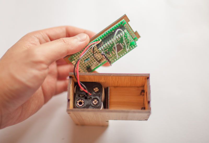
This is the sensor node guts in the enclosure. The protoboard sits underneath the lid. The lid have cutouts for the DHT11 sensor and LED.
The top side of the protoboard. The female headers are for the Moteino.
The back side of the protoboard showing the white LED and DHT11 (humidity/temperature sensor).
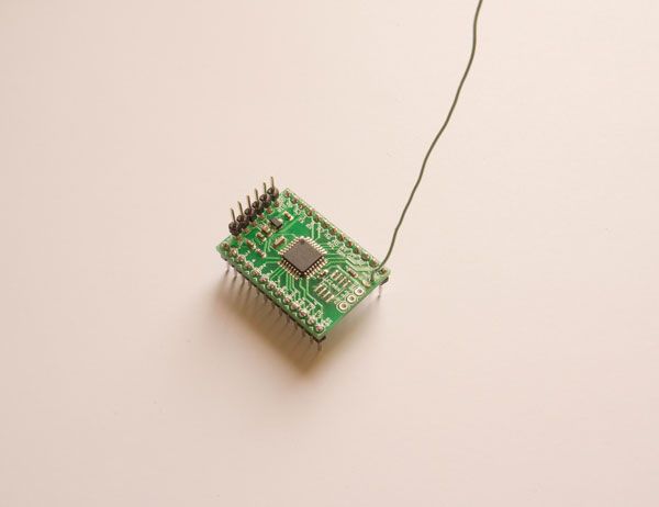
The Motieno on the protoboard:
Solder straight male headers to the Moteinos like so.
Measure the number of female pins (13 pins for each side) so it matches the number of male pins on the Moteino. Solder the straight female headers like this.
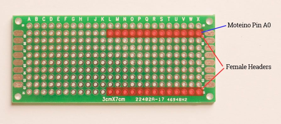
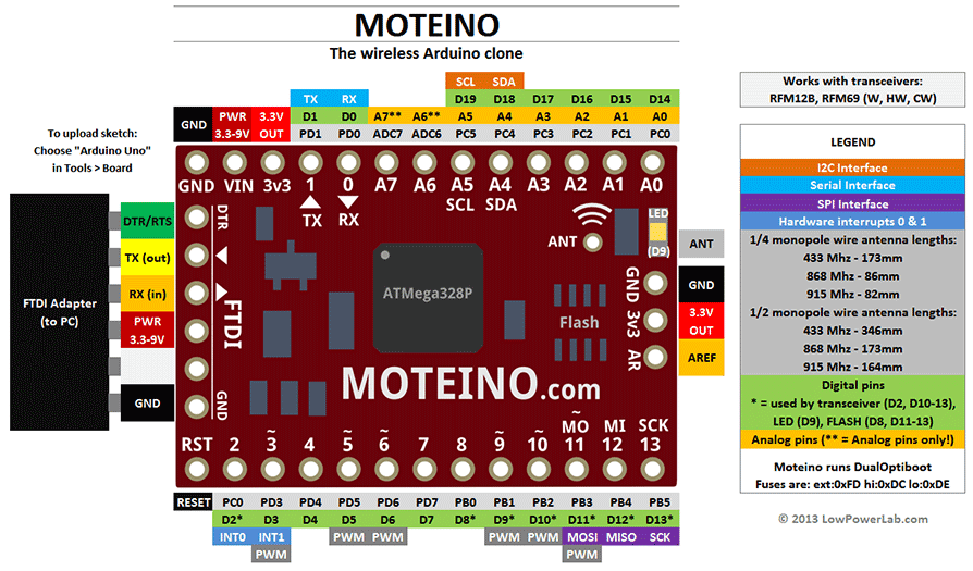
This is where our Moteino will reside. We will utilize both sides of the protoboard to keep the size small. Throughout the build, make a mental note on the pin numbers / co-ordinates. Here is a diagram of the pin outs of the Moteino:
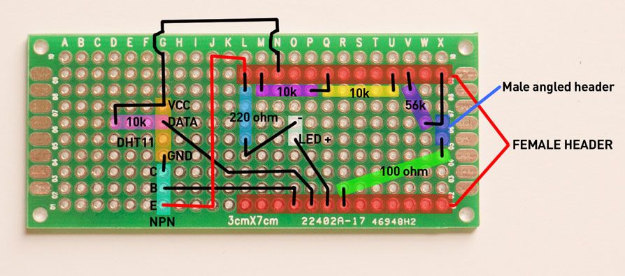
Here is a diagram of all the connections:
How do you sense soil moisture? The type of sensor we are building is a simple resistive sensor. We pass current into the soil via the probes and then read the voltage. Moist soil equals less resistance and dry soil equals more resistance. Here is a schematic of the soil moisture sensor circuit:
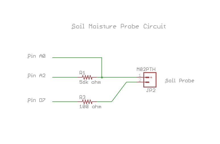
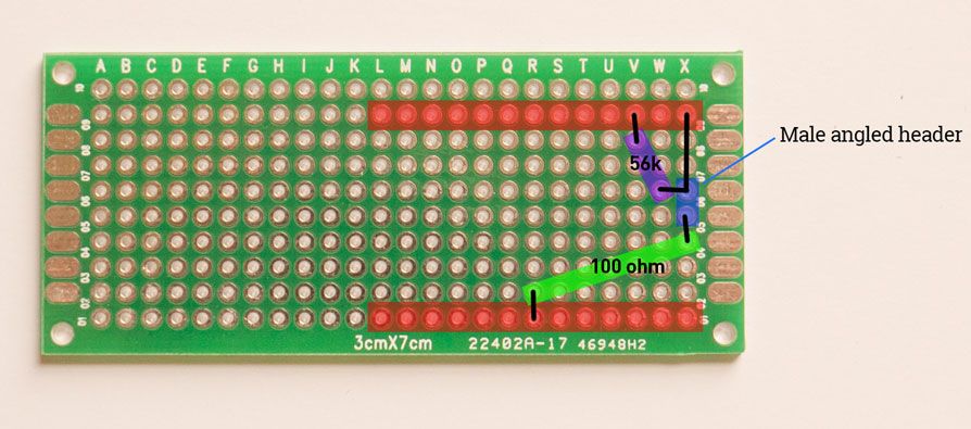
This design utilizes the digital pins on the Moteino to source and sink current. This way, we can alternate the current going through the soil which will help reduce electrolysis and minimize the corrosion of the probes. Take note of the pin assignments! Solder an angled male header, the 56k ohm, 100 ohm resistor like so. The angled male header will connect to the probe later.
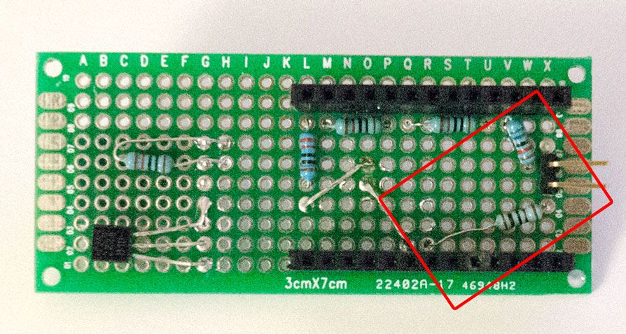
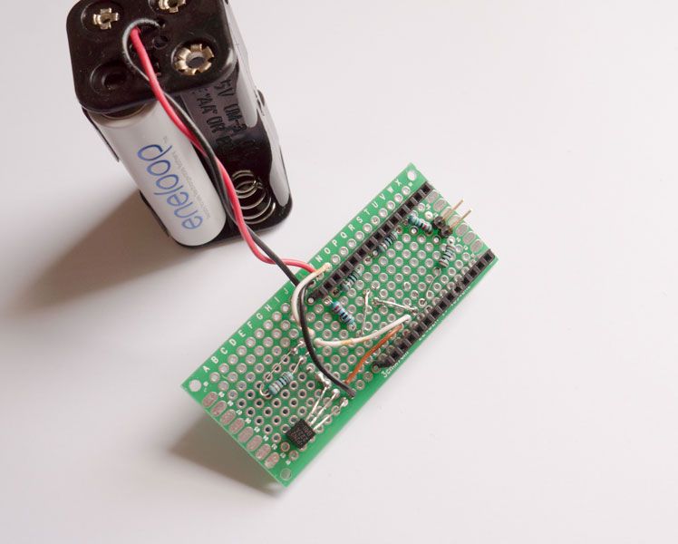
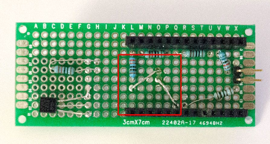
Flip the board over and solder the 56k ohm resistor to pin to A2, the 100 ohm resistor to pin D7. Solder a wire between the 56k ohm resistor and the angled female header to pin A0. You can bend the leads from the resistors to make the connection. Here is a picture of the underside of the protoboard with all the connections:
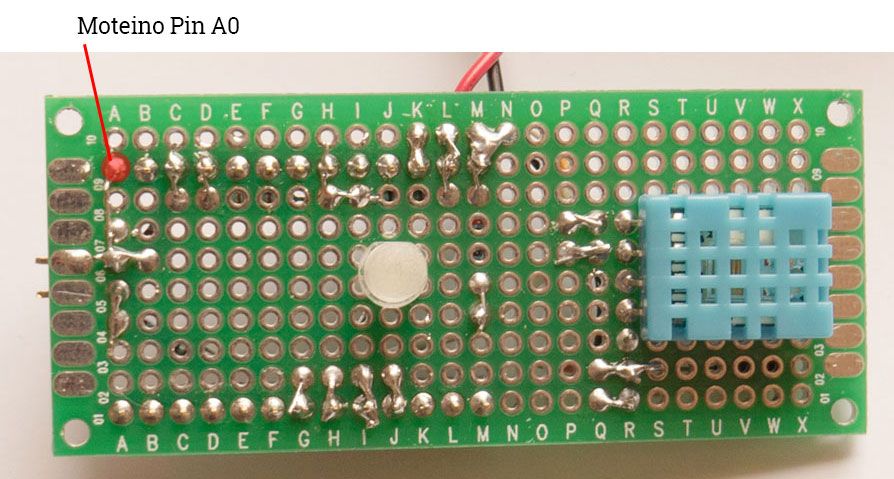
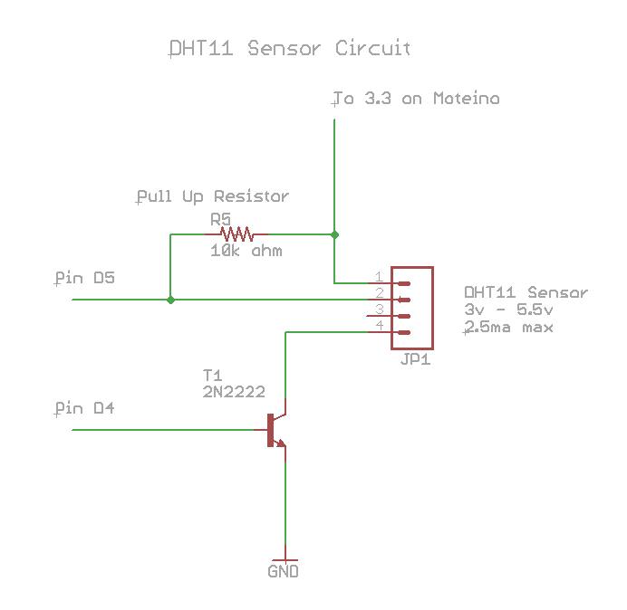
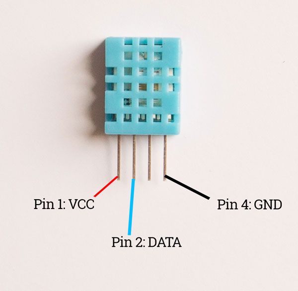
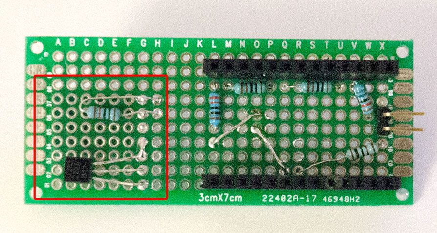
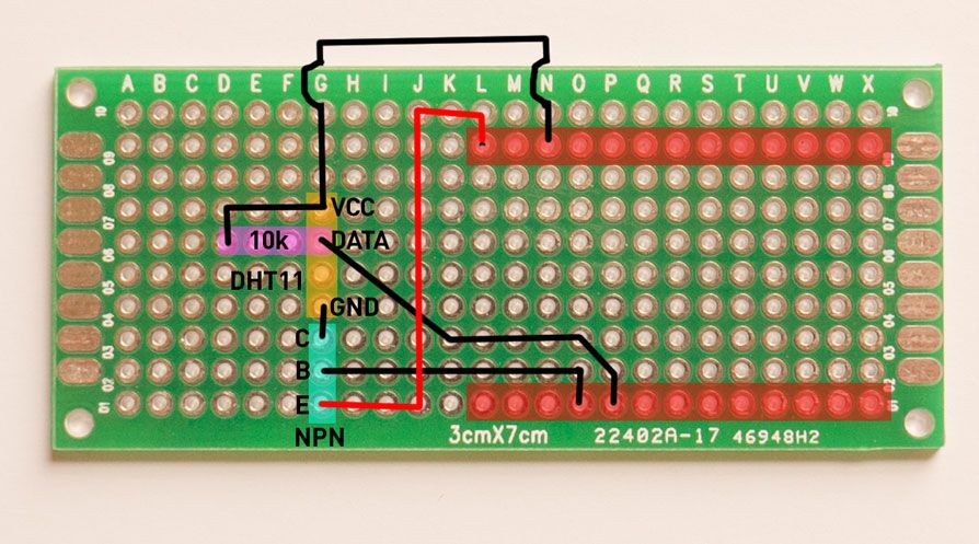
The DHT11 is a humidity and temperature sensor in one. It has 4 pins: 1 VCC, 2 DATA, NC, GND. The data pin needs a 10k ohm pull resistor. We will need the 2N2222 transistor to turn on and off the sensor so it doesn't drain out batteries when not in use.
DHT11 pins:
Solder the sensor down. Make sure you use the right holes or else it won't fit the enclosure!
Flip the board back and solder the 10k ohm pull up resistor and the 2N2222 transistor. The 2N2222 collector pin goes to the GND of the sensor. You'll need to use some wires for this: Solder the sensor VCC pin to 3.3 pin that corresponds to the Moteino pin, the sensor DATA pin to D5, the transistor base pin to D4, and the the transistor emitter pin to GND pin of the Moteino.
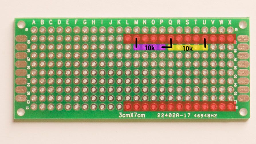
To ensure smooth, uninterrupted monitoring of your our plants, it would be very helpful to get a reminder when we need to change out the batteries for fresh ones. For our use case, detecting battery voltage would be a good way tell how much juice is left in our batteries.
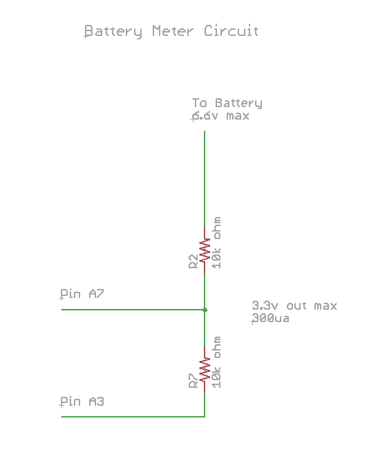
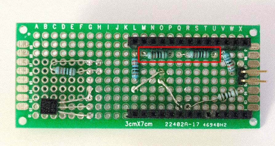
This is a simple 1:2 voltage divider that will allow the Moteino to read voltages from a maximum of 6.6v. To conserve battery life, we will use one of the pins on the Moteino to sink current (turn on the circuit) when we need to read the battery voltage.
Solder the 10k ohm resistors like so. Then solder one end of the resistor network to pin VIN, the other end to pin A3. Solder the connection between the 10k ohm resistors to A7.
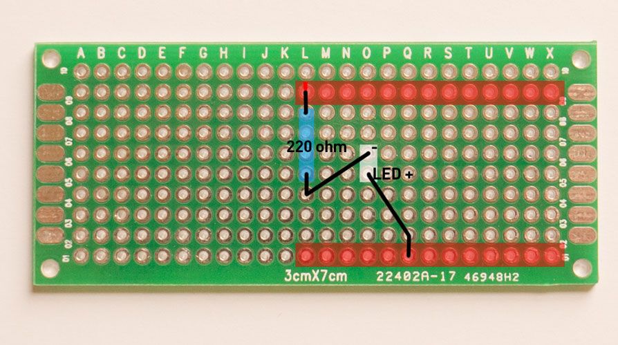
For the LED, we will drive it via pin D6. Solder the LED and resistor like this. Make sure the holes match mine or else the enclosure won't fit!
Here is a diagram of all the connections:
Now solder the battery holder. Connect the black wire to GND pin and red wire to VIN pin that corresponds to the Moteino.
2. Sensor Node Hardware